
Final Installation Check: 1. Ensure the fuel lines are tightly installed, with no fuel leaks or seepage. 2. After fuel line installation, ensure there are no air bubbles. If bubbles are present, check the tightness of connecting pipes and the oil-water separator. 3. Confirm power connections are secure. All wiring must be properly connected, insulated, and firmly fixed. 4. Ensure adequate space is left between the device and surrounding components for ventilation.
step 1
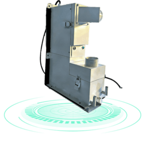
Determine the installation location: Choose a safe and level location on the vehicle. Refer to the provided diagram for the installation position of the main unit. Complete the installation and secure it firmly.
step 2
Disconnect the vehicle’s fuel tank outlet pipe. Use the provided fuel hose (16mm OD, 12mm ID) to connect the fuel tank outlet to the device’s inlet. Adjust the water pump and fuel pump flow meters to normal operating levels and perform a flush with cleaning solution.
step 3
Open the designated valve or pressure gauge on the device, setting it under the valve body as needed for control. Ensure the valve seal is properly seated in the valve body, avoiding contact with the self-locking mechanism. The valve must remain sealed when closed.
step 4
Make electrical connections: Connect the device red wire to the vehicle’s positive terminal (red), the device black wire to the vehicle’s negative terminal, and the extension wire (short wire) to the corresponding connector. Use insulating tape to wrap the connections. After completion, turn on the device power within the appropriate range, start the subsystem function; a red light indicates operation.